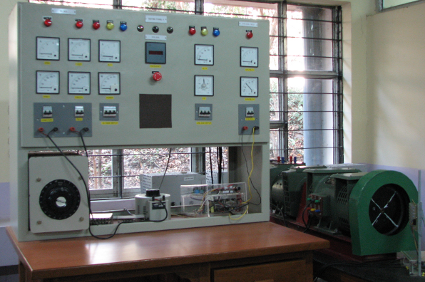

The setup in this virtual laboratory can be used for the following experiments:

DC Machine starting and speed control

Control of AC-DC converters for electrical machine control

Effect of load and excitation control on synchronous alternator output voltage.

Principle of synchronization of a synchronous machine to the power grid.
The target groups for these experiments are:

Senior Under-Graduates (Electrical Engineering)

Post-Graduates (Power Electronics, Power Systems, Electrical Machines and Drives)

Practising Power Engineers
Before we begin our experiments, let us list out the requirements on the user side
 Web browser : Mozilla Firefox(3.0+), Internet Explorer(6+), Konquerer
 Recommended Bandwidth
 A lot of enthusiasm !
The setup consists of a controlled prime mover (DC motor - separately excited) coupled to a synchronous generator which is to be connected to a power grid. The synchronous generator is excited by a controlled AC-DC power electronic converter. A separately excited DC motor is used as a prime mover. The armature of the DC motor is fed from a (controlled) three phase thyristor rectifier. The DC voltage to motor field is also provided by a similar controlled rectifier. All the interconnections of the components are made inside the panel. A measurement card is enclosed inside the panel, which is used to measure and scale down the voltages and currents of the motor and generator.

Synchrnous generator : 1 kW, 1.25 kVA, 3 phase, 415 V, 1500 rpm, 0.8-0.9 PF, 50 Hz, cylindrical Rotor, Excitation max. 110 V without damper bars shaft extension on both sides

DC motor : 3 HP, 220V, 1500rpm, shunt-wound, foot mounted, self fan cooled.

AC-DC Converters for (a) DC machine armature (b) DC machine field and (c) Synchronous Machine Exciter

Load Bank : Three switchable load banks are provided each having a rating of *1440 W, 166VAr, 3ph*.

Operating System : Presently, we are using QNX neutrino 6.3 version. QNX is used to run the programs in hard real time. In our set up QNX is used to generate control signals to hardware devices like 3 Phase Thyristor full bridge rectifier,etc.
QNX is a commercial Unix-like real-time operating system, aimed primarily at the embedded systems. As a microkernel-based OS, QNX is based on the idea of running most of the OS in the form of a number of small tasks, known as servers. This differs from the more traditional monolithic kernel, in which the operating system is a single very large program composed of a huge number of "parts" with special abilities. In the case of QNX, the use of a microkernel allows users (developers) to turn off any functionality they do not require without having to change the OS itself; instead, those servers are simply not run. This gives the QNX a capability to run programs in real time based on priority.
Linux is an UNIX based operating system. It is not a real time operating system like QNX. In our set up Linux machine serves as a interface between the QNX system, which controls the hardware, and the user. The server is set up on this Linux machine which sends and receives data from the user to QNX system and vice-versa

Voltage and current measurement card : This card takes the voltages and currents as inputs and converts them into digital format. The card can measure following :
| Type of quantity | Number of measurement ports available | Nominal value |
|---|---|---|
| AC voltage | 6 (2 three phase systems) | 400 V (L-L) |
| AC current | 3 | 4.33 A |
| DC voltage | 2 | 220 V |
| 1 | 400 V | |
| DC current | 2 | 2 A |
| 1 | 10 A |
This voltage in digital format then goes to PCI card.

PCI card : Advantech 1710 HG
Before you proceed for the actual experiment it is useful to revise at the theory behind the experiment. This section will take you throgh the topics which you should be aware of before going further. You are directed to references for more exhaustive coverage.